

ReelToLogic
Still have my reel-to-reel
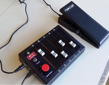
I was inspired by some of the postings here on VI-Control and some other forums to try building my own MIDI CC Controller. In addition to five 100mm Sliders I wanted to add a foot pedal that I could assign to CC1 or CC11 so that I could play string or other VI parts with both hands while still controlling Modulation or Expression.
So I bought a Nectar NX-P Foot Pedal (only $20; https://www.musiciansfriend.com/keyboards-midi/nektar-nx-p-universal-expression-pedal) hoping I could make that work with the Teensy 3.2 controller. It turns out it contains a variable resistor (potentiometer) similar to the other slide potentiometers I used in the main module, so it was very easy to incorporate. The 1/4" Stereo (TRS) connector plugs into my main box. On my unit I set the polarity to the #1 setting (there's a switch on the bottom) and I found that the "Tip" was the wiper so I connected that to an analog input, the "Ring" got 3.3 volts and the "Sleave" went to ground. I turned the "sensitivity" knob on the side fully CCW and I got smooth output of CC's from 0 to 127 over the full travel of the pedal.
I also included a 5-position selector switch so that I can pre-program 5 different sets of CC's and select them on the fly. I've wired that in, but haven't finished debugging the code to do that yet so right now I just have one set of CC's. I also wanted a device that was very compact so I purchased a plastic box that was just a little over 5" x 7" in size. It was so small that I had to do some minor machining just to make the 100mm travel slide pots fit inside it!
I was very excited at how easy and inexpensive it was to incorporate a foot controller into my project so I wanted to share this. I should note that I also have one of the 100mm sliders assigned to CC1, since my hands can do a more precise job of control than my foot. Depending on how skilled I get with my foot, it may be that I use the pedal more for "playing" than for recording - we'll see. It certainly is nice to have when playing! There are lots of other threads that discuss building these simple MIDI CC controllers but if anyone wants more info on this project just let me know.
Attachments
Last edited: